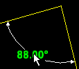
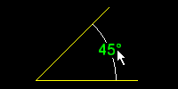
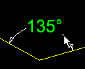
 Dimension Add Angle ( Drawing Editor )
Tool summary :
Also see :
- Angle dimensions (topic)
- Edit Angle Dimension (window containing angle dimension settings)
page 1 | contents | objects > angle dims > | objects -- angle dims | xxx add
 Setup and defaults :
Home > Project Settings > Fabricator > Detailing > Dimension Settings > the " General " tab:
Defaults for auto detailing:
- Automatically detailed dimension labels use the " Dimension label pen color " and character height and width/height ratios set in Drawing Presentation . If you are using the ' SDS2 ' font , the " Dimension label pen color " also sets the default stroke weight of that font.
Dimension leg and line defaults:
- The " Dimension pen color " for the legs and lines of automatically detailed and user-added dimensions, including angle dimensions, is set in Drawing Presentation . To change this on individual drawings, you can Angle Dimension Edit or Angle Dimension Edit All then reset the " Pen color " on the edit window.
page 1 | contents | objects > angle dims > | objects -- angle dims | xxx add | top
 Adding an angle dimension :
|
Before using this tool:
Optional: On the Layer Panel, select the layer that you want to add the dimension to. This is optional because, if you don't select a layer, Dimension Add Angle will assign the angle dimension to a default layer -- for example, to the " User Annotation " layer. The layer to which an angle dimension is assigned can be changed on the Edit Angle Dimension window.
Optional: If you are planning on using radians as the " Measurement units ," the " Angle dimension precision " in Dimension Settings should be at very least 1.

|
1 . Invoke Dimension Add Angle . |
|
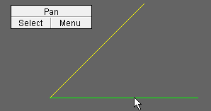
2 . Left-click ( Select ) one of the lines or polygon lines or construction lines that you want to measure the angle between. |
|
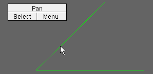
3 . Left-click ( Select ) the other line or polygon line or construction line that you want to measure between. |
|
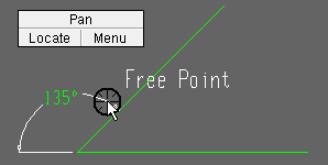
4 . Dimension Add Angle draws a preview of the angle dimension in whatever quadrant the target ( |
|
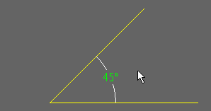
5 . The angle dimension is drawn between the two lines being measured. It is drawn in the quadrant that the target was in when you located the point in step 4. |
Note 1: To invoke Dimension Add Angle :
Method 1 : Click the Dimension Add Angle icon. The icon can be taken from the group named ' Objects -- Angle Dimensions ' and placed on a toolbar (classic) or the ribbon (lightning).
Method 2 : If " Drawing Editor layout style " is ' Classic ', you can use the menu system to choose Objects > Angle Dimensions > Add .
Method 3, 4 or 5 : Dimension Add Angle can also be invoked using a keyboard shortcut , the context menu , or a mode . For the ' Lightning ' layout style, configuration of the interface is done using Customize Interface .
Note 2: If the two lines that you select (steps 2 and 3) are parallel to one another, you cannot measure the angle between them, and you will get an alert like the following. It is not required that the two lines meet one another or cross one another, but they must not be parallel.

These lines do not intersect. 

Note 3: If, in step 4, you left-click when the point location target (
) is snapped to the vertex of the lines being measured, you will get the following alert. Press " OK " to dismiss the alert, then move your mouse pointer (
) so that the target (
) snaps to the location where you want the dimension line of the angle dimension.

Cannot place at center. 

Tip 1: Angle dimensions added using this procedure can be quickly removed by using Undo .
Tip 2: You can Shift -drag an angle dimension label to a new position.
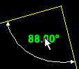
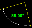
1 . Hold down Shift and press the left mouse button ( Select ) to grab
the dimension label.2 . Drag the dimension label to a new location. 3 . Release the mouse button when the dimension label is where you want it. Tip 3: You can drag an angle dimension label to rotate it. Doing so updates the entry made to " Rotation (degrees) " on its edit window.
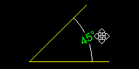
1 . Grab the angle dimension label to rotate it. 2 . The 4-way mouse pointer indicates that directional movement is unconstrained. Tip 4: You can drag an angle dimension line (the line with arrows) to a new quadrant and thus cause the angle dimension to be recalculated.
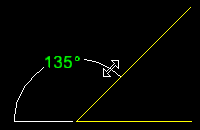
1 . Grab the angle dimension line and drag it to a different quadrant. 2 . The dimension label is recalculated. Tip 5: You can drag an angle dimension line (the line with arrows) to resize the dimension line. You need to drag it within the same quadrant.
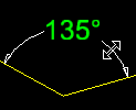
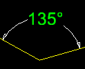
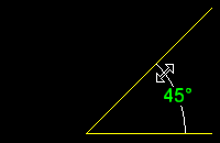
1 . Grab the dimension line of the angle dimension. 2 . Drag the angle dimension within the same quadrant. 3 . The dimension line is resized. Degrees stay the same.
page 1 | contents | objects > angle dims > | objects -- angle dims | xxx add | top
